Thanks for the photos floydfan.
My initial reaction is that the transformer looks small. Which makes sense as we're not talking large power levels here. And this is the entry level model.
It's easy to see and instinctively feel that larger transformers would / could / should improve the sound quality.
At a price. But a relatively modest price, especially if DIY'd.
Phono 1 MC
-
Lindsayt
- Posts: 4230
- Joined: Fri Jul 13, 2012 9:06 pm
- Has thanked: 1103 times
- Been thanked: 699 times

-
Daniel Quinn
- Posts: 8586
- Joined: Thu Jul 12, 2012 7:16 am
- Has thanked: 24 times
- Been thanked: 399 times
Re: Phono 1 MC
Am still trying to get my head round the physics of the power supply; just for fun.So help always welcome.
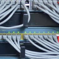
In the transformer from my P1 the yellow and black wires go to the rectifier. So this should be either 25 or 50 volts. I assume 25 as the board uses 20v. The red and orange are joined ,I assume putting the secondaries into parallel configuration, then the joined wires are soldered onto the 0v bar. I can't seem to get my head round this. I am also thinking about the capacitor arrangement but I will give this more thought. I probably don't need the theory to improve the P1 but it is interesting.
In the transformer from my P1 the yellow and black wires go to the rectifier. So this should be either 25 or 50 volts. I assume 25 as the board uses 20v. The red and orange are joined ,I assume putting the secondaries into parallel configuration, then the joined wires are soldered onto the 0v bar. I can't seem to get my head round this. I am also thinking about the capacitor arrangement but I will give this more thought. I probably don't need the theory to improve the P1 but it is interesting.
-
Daniel Quinn
- Posts: 8586
- Joined: Thu Jul 12, 2012 7:16 am
- Has thanked: 24 times
- Been thanked: 399 times
Re: Phono 1 MC
Im going to be of no use. I simply copied what the doc had done without understanding it.
But then again , he didn't understand the legal work I did for him , so we were quits
But then again , he didn't understand the legal work I did for him , so we were quits

- These users thanked the author Daniel Quinn for the post:
- slinger (Tue Jul 06, 2021 2:51 pm)
-
Geoff.R.G
- Posts: 1569
- Joined: Thu Aug 11, 2016 2:46 pm
- Location: Denham UK
- Has thanked: 133 times
- Been thanked: 483 times

Re: Phono 1 MC
Sounds like the transformer has two secondary windings Black/Red being one and Orange/Yellow the other. If orange/red are connected the voltage between black and yellow should be the sum of the rated voltages for the two windings. This if each secondary is rated at 25V I would expect to see 50V across black and yellow. However, as you say, if the windings are in parallel you would have 25V but then why use a transformer with two secondaries and operate them in parallel?floydfan wrote: ↑Tue Jul 06, 2021 1:09 pm Am still trying to get my head round the physics of the power supply; just for fun.So help always welcome.
In the transformer from my P1 the yellow and black wires go to the rectifier. So this should be either 25 or 50 volts. I assume 25 as the board uses 20v. The red and orange are joined ,I assume putting the secondaries into parallel configuration, then the joined wires are soldered onto the 0v bar. I can't seem to get my head round this. I am also thinking about the capacitor arrangement but I will give this more thought. I probably don't need the theory to improve the P1 but it is interesting.
Re: Phono 1 MC
Good question Geoff. The transformer also had 2 primaries. Maybe it was just the transformer the Doc liked. He had definite reasons for what he did but I did not always follow them. The bit that has me perplexed is why the joined leads are soldered to the 0 volt rail. On second thoughts in parallel you get higher current, maybe that is important.
-
Latteman

- Posts: 1222
- Joined: Tue Aug 14, 2018 7:20 pm
- Location: S. Yorkshire
- Has thanked: 555 times
- Been thanked: 299 times
- Contact:
Re: Phono 1 MC
Unsolder the wires to the phono board at the regulator board before u power on - u can then check u get 20v - & + when current passes through the transformer- bridge rectifier- caps and then the regulator
This way no damage to the sensitive board and worst case scenario is a blown lm337 or 317
This way no damage to the sensitive board and worst case scenario is a blown lm337 or 317
Analogue Source -
Denon DP47f; AT-VM95SH
GL-59; ARB uni pivot; AT- Signet
Ifi Zen Phono
Doug Self balanced Pre amp
Akai 4000DS mk2 R2R
Digital Sources- Argon Pi4 v2; IfI iUSB 3.0, Ifi Neo idsd Dac;
Tidal / Radio Paradise
Amplification Nva 300va mono blocks
Speakers Lii Audio F-15 in Open Baffle; Ls6
Weiduka AC8.8- for digital sources
Mini BMU for analog sources
-
karatestu

- Posts: 5965
- Joined: Sun Jan 08, 2017 4:40 pm
- Location: North Yorkshire
- Has thanked: 1876 times
- Been thanked: 1400 times
Re: Phono 1 MC
The two wires which are joined together and soldered to 0V form a centre tap which is exactly half way between the two ends. Split rail psu's like this produce a positive and negative voltage relative to the centre which is 0V. The two secondary windings are simply wired in series with the point that they join being the centre tap.
If you measure between the yellow and 0V it should be around the rated voltage of the transformer. Same with the black to 0V. Between yellow and black the voltage should be exactly double of what you measured previously
Hope that makes sense.
If you measure between the yellow and 0V it should be around the rated voltage of the transformer. Same with the black to 0V. Between yellow and black the voltage should be exactly double of what you measured previously
Hope that makes sense.
DIY FREE ZONE