Page 3 of 3
Re: Poundland Amp Project
Posted: Mon Jul 05, 2021 8:41 am
by SteveTheShadow
Geoff.R.G wrote: ↑Mon Jul 05, 2021 7:32 am
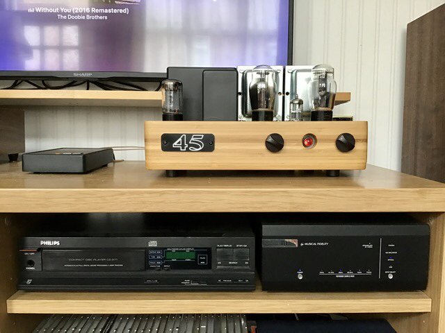
It looks amazing but, as an engineer, I think the output transformer on the right should be slightly closer to the edge so that it’s centre line coincides with that of the valve in front of it.
The valves have to be the width of 1.5 envelopes apart so they can’t go any closer to each other than they are, otherwise they will heat each other by radiation. Then there is the small double triode at the front to think about. It can’t go any further forward or its socket would foul the lamp or any further towards the power valves due to heating by radiation. The valves are equally offset from each of their respective output transformers.
The problem you are seeing on the photograph, is a much bigger one: the controls are offset to the right from the three valves. IMO it was an unforgivable error on my part, and was so easily avoidable given a bit of forethought and some old fashioned ‘measure twice, cut once’ policy. I suspected that somebody would notice it eventually, but what’s done is done and I’m just going to have to suck it up I’m afraid, because there is no way I’ll be rebuilding for the sake of three slightly misplaced control mountings. Let’s just call it a lovable quirk.

Re: Poundland Amp Project
Posted: Mon Jul 05, 2021 9:50 am
by Geoff.R.G
SteveTheShadow wrote: ↑Mon Jul 05, 2021 8:41 am
Geoff.R.G wrote: ↑Mon Jul 05, 2021 7:32 am
It looks amazing but, as an engineer, I think the output transformer on the right should be slightly closer to the edge so that it’s centre line coincides with that of the valve in front of it.
The valves have to be the width of 1.5 envelopes apart so they can’t go any closer to each other than they are, otherwise they will heat each other by radiation. Then there is the small double triode at the front to think about. It can’t go any further forward or its socket would foul the lamp or any further towards the power valves due to heating by radiation. The valves are equally offset from each of their respective output transformers.
The problem you are seeing on the photograph, is a much bigger one: the controls are offset to the right from the three valves. IMO it was an unforgivable error on my part, and was so easily avoidable given a bit of forethought and some old fashioned ‘measure twice, cut once’ policy. I suspected that somebody would notice it eventually, but what’s done is done and I’m just going to have to suck it up I’m afraid, because there is no way I’ll be rebuilding for the sake of three slightly misplaced control mountings. Let’s just call it a lovable quirk.
I'd missed that the controls weren't in line but I probably reasoned that it was deliberate to avoid the valve bases. It still looks good and most people wouldn't notice.
Re: Poundland Amp Project
Posted: Mon Jul 05, 2021 11:26 am
by CycleCoach
Looks pretty good to me.
Re: Poundland Amp Project
Posted: Mon Jul 05, 2021 2:42 pm
by SteveTheShadow
- F9ABFB4E-7256-4605-8A16-AEB48EA5890C.jpeg (111.39 KiB) Viewed 1127 times
Baseboard and feet fitted after changing resistor in power supply. Job done.
Re: Poundland Amp Project
Posted: Tue Jul 06, 2021 12:05 am
by antonio66
antonio66 wrote: ↑Mon Jul 05, 2021 2:12 am
And looking very nice Steve, my only niggle would be the red, presumably on/off switch. The base board, what will go underneath it and what will go between the amp and baseboard?
Mis-understanding by me, thought you meant a separate base board for it to stand on, and seeing the amp at a better angle I realise it's the on/off light.
Re: Poundland Amp Project
Posted: Wed Jul 14, 2021 6:29 pm
by SteveTheShadow
From the AT forum.
Cressy Snr wrote: ↑Sun Jul 04, 2021 10:22 pm
… the physical layout of the two 45s and the single ECC88 driver stage, means it is completely impossible to mess with; there simply isn’t the room. I took a conscious decision with this amp to deliberately make it difficult, if not impossible to modify. There can be no alternative drivers apart from those in the ECC88 family. There can be no octal driver substitutions, no room. There can be no DC modules for the 45 filaments, no room. No HT regulators: solid state or otherwise, no room. No fancy stepped attenuator, no room. The amp is basic, is what it is and is forced by its small size to remain so, which is good.
Well I didn’t bargain for the scope that a 5V rectifier on an octal socket scheme would give for endless plugging and unplugging.

Anyway I’ve taken the initiative, and shut down that particular avenue good and proper, with the aid of a British B5 valve socket and 0.47R power resistor to give near as dammit a 4V/2A rectifier spec.
The 4V transformer I have is too big to fit, which is actually a good thing, because the 0R47 resistor in series with the 5V transformer secondary means only 4V/2A spec unless the resistor is changed. The resulting inconvenience stops any chance of me even thinking about classic Mullard FW4-500 rectifiers and their 3A ilk.
My sole Mazda UU4 is now in residence in the rectifier position. It is the only 4V, full wave rectifier valve I have. Fecking about is now shut down on all fronts.

- E5CEF4A3-5E60-4373-A583-BA995EE197BD.jpeg (90.13 KiB) Viewed 948 times
Peace. Perfect peace.